Page 1 of 2
ST2 transplant process
Posted: Thu Aug 07, 2025 3:50 am
by Slowmo
- weekend fun.jpg (195.74 KiB) Viewed 284384 times
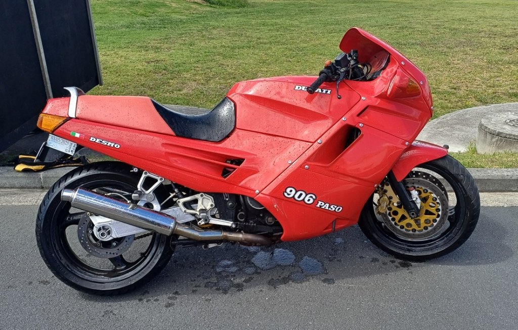
Bought this old girl in Feb with 92k km on the clock, was hoping to crack 100k but was leaking/burning oil badly. I rode it nearly 4k km before doing a teardown inspection and discovered that it was quite worn internally - loose crank plug, badly pitted 3/4/5 gears, notchy mains bearings, worn exhaust valve guides. Given the low budget available for rebuild I decided to install a 2001 23k km ST2 engine instead. Currently giving that a clean up and inspection before begining the process of transplanting into the 906 frame. Will post details as I go.
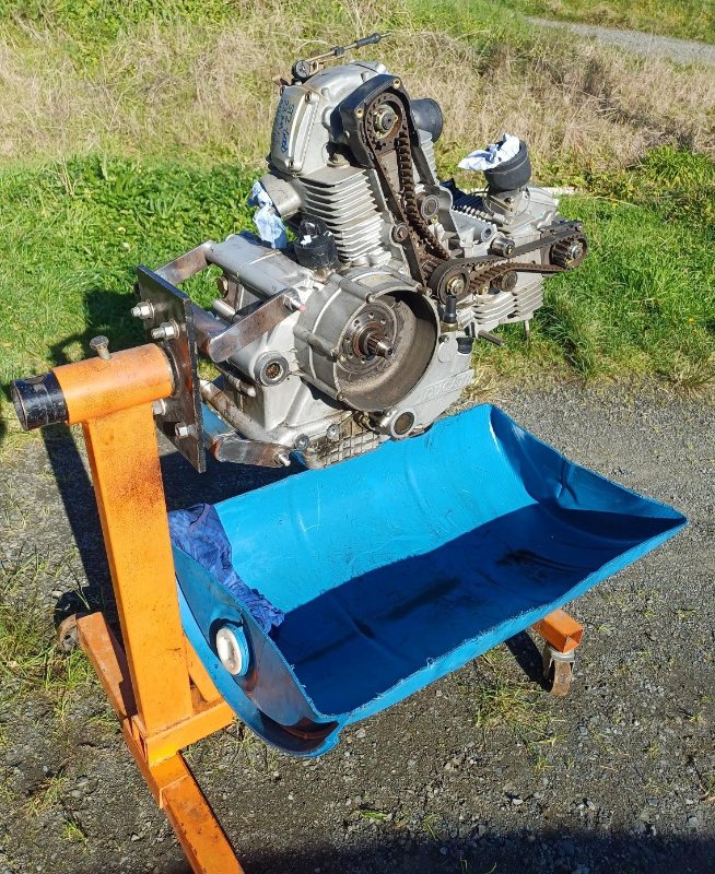
- ST2 transplant.jpg (212.76 KiB) Viewed 284384 times
As the bike came with 41 FCR's I will be staying with those for fuel delivery.
The 3 phase alternator is going to require a better regulator/rectifier.
Ignition is going to be a bit of an experiment with the open source Speeduino ECU.
The wheels were converted to 17" by PO.
Re: ST2 transplant process
Posted: Thu Aug 07, 2025 8:31 am
by Tamburinifan
Will be interesting to follow.
https://www.ignitech.cz/en/vyrobky/tcip/tcip.htm
Another possibility for ignition.
Has maps for Ducati.
Re: ST2 transplant process
Posted: Thu Aug 07, 2025 7:11 pm
by Slowmo
Thanks for the Ignitech link Gert, it is a very sensible solution but I am keen to pursue a different route (i.e. I have one in my drawer from another project). If Speeduino proves unreliable during test runs will go for Ignitech.
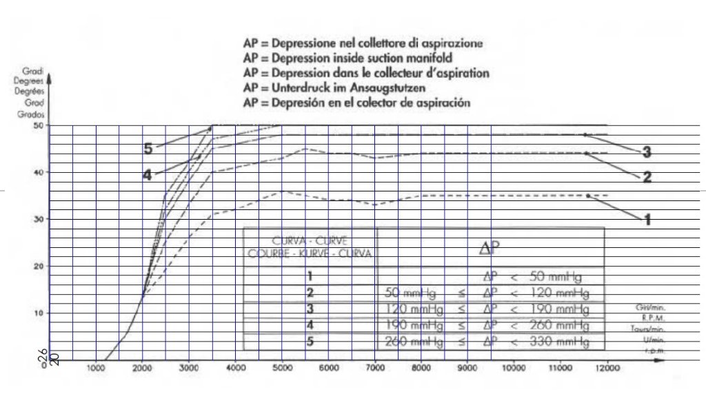
The service manual for the 906 has an ignition map based on MAP load. I overlaid some gridlines to create data points for the 3D ignition curve.
- advance curve.jpg (100.55 KiB) Viewed 284366 times
Re: ST2 transplant process
Posted: Fri Aug 08, 2025 8:18 am
by Tamburinifan
Ok.
Curve 1 the most suitable for your engine.
Re: ST2 transplant process
Posted: Fri Aug 08, 2025 9:06 pm
by Slowmo
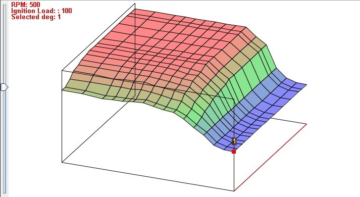
- 3D Ignition map.jpg (50.97 KiB) Viewed 284338 times
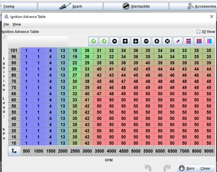
- Tunerstudio Spark Advance.jpg (107.76 KiB) Viewed 284338 times
Spark advance settings translated from OEM Digiplex 2s curves to the Tunerstudio table.
Re: ST2 transplant process
Posted: Sat Aug 09, 2025 7:04 am
by higgy
Re: ST2 transplant process
Posted: Sat Aug 09, 2025 7:24 am
by Slowmo
Yes, the Speeduino is setup using the Tunerstudio software. Crank rotation is natively handled as a 5v square wave Hall effect signal, however a separate VR board can be used to process the ST2 signal. I don't have a VR board so will adaptor a ZF hall sensor instead, still reading the timing gear at 48-2 cam speed tooth pattern. Speeduino also does a tachometer output so that will help with one of the major conversion issues.
Re: ST2 transplant process
Posted: Sun Aug 10, 2025 6:32 am
by higgy

cool beans
Haave an early version around here someplace

Re: ST2 transplant process
Posted: Sun Aug 10, 2025 8:06 am
by Tamburinifan
Re: ST2 transplant process
Posted: Mon Aug 11, 2025 11:07 pm
by Mc tool
Inc FCR's sounds like a good score.
Is the ST2 dimensionally the same ? (Cant think why it wouldnt be )
Re: ST2 transplant process
Posted: Tue Aug 12, 2025 8:12 am
by Slowmo
No the ST2 engine is wider around the swingarm pivots and the lower rear engine mount. A fair few mm of aluminium has to be milled off to make it a bolt in job.
Re: ST2 transplant process
Posted: Thu Sep 18, 2025 11:15 pm
by Slowmo
Unfortunately the ST2 motor was not shipped complete as expected and had to fit a flywheel afterwards. Below are dims for making your own tool if so desired, needed 270Nm to do up the nut.
Note a blind puller was used to remove the outer pivot bearings but the inner one was left inplace to guide the "width adjuster" tool.
Re: ST2 transplant process
Posted: Thu Sep 18, 2025 11:49 pm
by Slowmo
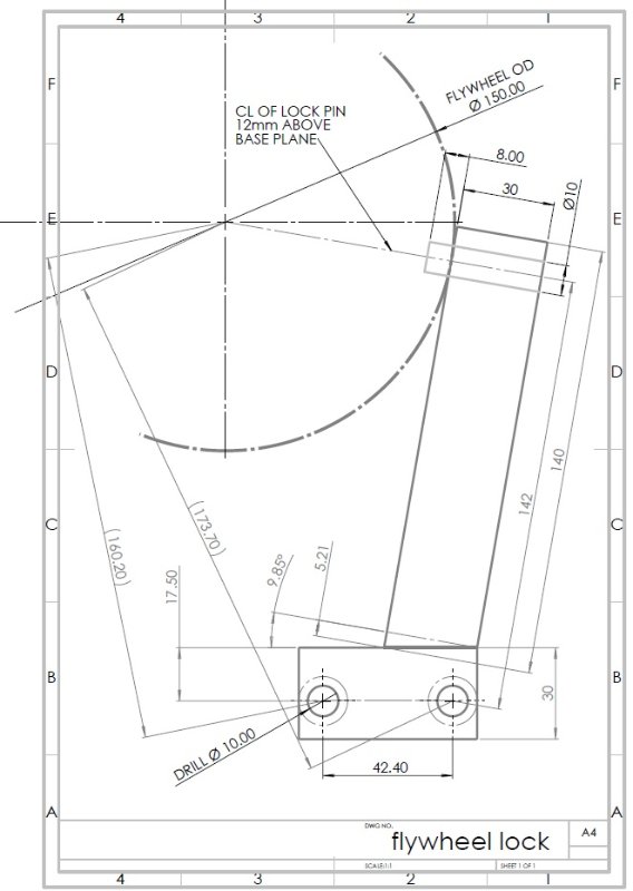
- flywheel lock tool dims.jpg (50.45 KiB) Viewed 11133 times
Re: ST2 transplant process
Posted: Mon Sep 22, 2025 8:14 pm
by Slowmo
Nothing is more infuriating than carefully laying everything out in the morning, putting all the appropriate parts in little labelled plastic bags only to unbeknowingly drop one of the little orings - unfortunately the smallest one that was totally silent as it bounced out the garage door and out onto the sunlit driveway. Lost almost 3/4 of an hour and all of my patience retracing steps and looking under/in things for that tiny o-ring that I knew I had "put" in the bag.
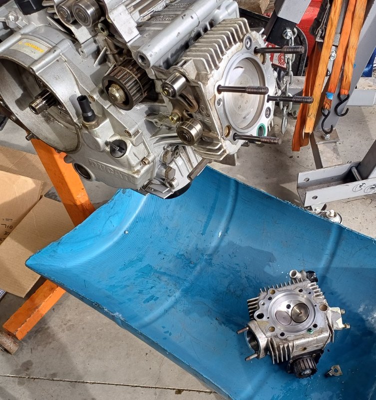
- new orings finally.jpg (158.22 KiB) Viewed 10890 times
At least it's all back together now and the casing mods can start without the risk of swarf getting in the cases.....
Re: ST2 transplant process
Posted: Mon Sep 22, 2025 8:16 pm
by Slowmo
For those of you with machining experience please be forewarned, the following may be upsetting.
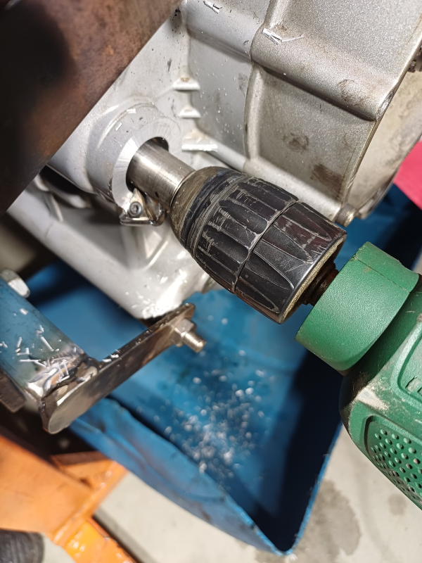
Didn't want to mount the engine in a mill nor attempt to cut freehand so have gone for a halfway house, the width adjuster tool shaft is a touch under 20mm for easy running on the inner needle rollers left inside the casing, the tip shaves the casting material nicely however chatter is "significant". Might adjust the rake of the tip once I get to the "finishing" cut.
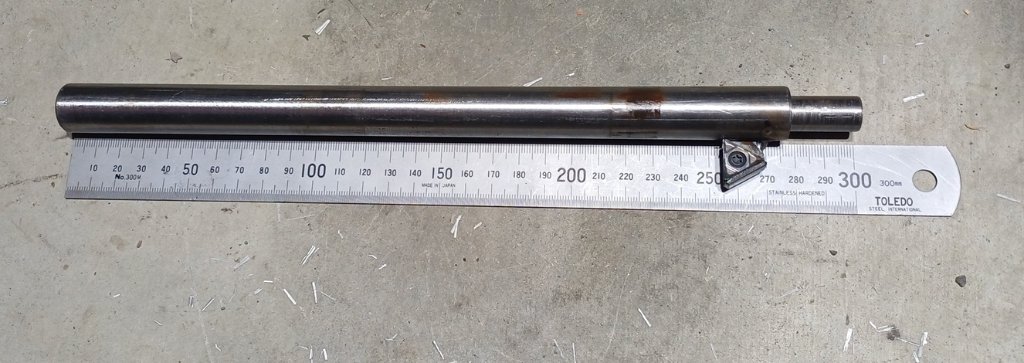
- Width adjuster tool.jpg (342.86 KiB) Viewed 10890 times
- chatter anyone.png (954.17 KiB) Viewed 10890 times
It's not a bad start, will measure the 906 casing extremely carefully and transfer the dims to this one and cut till the appropriate marks. If done patiently I should not need additional shims.
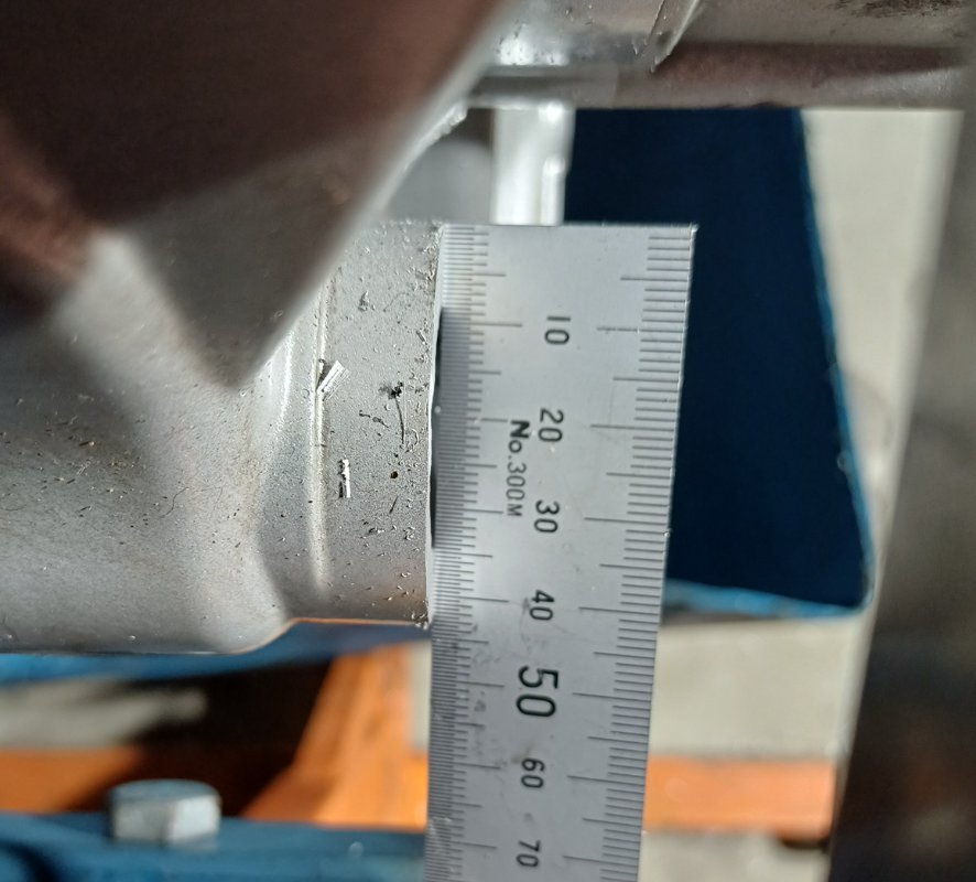
- rough but effective.jpg (89.59 KiB) Viewed 10890 times
One upside from having a non standard 17" rear wheel is the rear sprocket offset from centerline matches the ST2 output shaft front sprocket centerline offset.